Utility Creation Tools
In this tutorial, we explain how to use the utility Editor module of our creation tools. This editor contains a few similar elements to Entity Creation Tools and some concepts may be found in both tutorials.
You can use utility Editor in two ways:
-
To configure the utility AI in your game. You can essentially create the whole system, but certain logic must be provided in code:
-
the code behind
considerations -
the code behind
behaviors
-
-
To quickly prototype a particular utility AI without the actual game.
-
You can setup the system and play with it in the editor. This can help you iteratively design the ultimate configuration that works for the game.
-
Utility Editor uses considerations and behaviors as references to things that exist in the game. The editor does not use or require their code (logic). Those elements can be referenced by the name identifier in the editor. However, in the actual game you need to provide the code. This is highly specific logic so it cannot come with a predefined implementation. This tutorial will go back to this issue in Section Using the configuration in your game.
|
Getting started
To create a new configuration file, click the Create new project button or open an existing project by clicking the Open project button.
In this manual page, we will show you how to configure the system from scratch. You can save your project anytime and open it to continue working from where you saved.
Overview
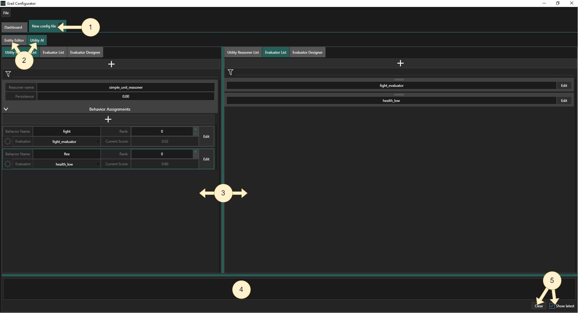
(1) File tab - you can see the opened file. You can also close it here.
(2) Editor tabs - when creating the utility system, you will be working with both of them, but in this tutorial we’ll focus mainly on the Utility AI tab. Too read more about using Entity Editor tab to create Entities, see Entity Creation Tools.
(3) Main columns - both columns of this view can be independently switched between three different views: Utility Reasoner List, Evaluator List and Evaluator Designer.
(4) Console - a small output log window.
(5) Console buttons - you can clear the output log here and also set the window to auto-scroll ("Show latest" checkbox).
Utility Reasoner List
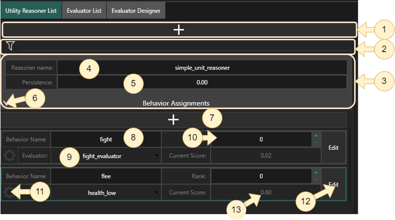
In this view, you can create new utility reasoners and their behaviors, assign utility evaluators and debug the final reasoner configuration. More about utility reasoners here
(1) Add button - creates a new utility reasoner.
(2) Filter - allows you to filter the displayed reasoners by name.
(3) Utility reasoner view - here you can assign a name to your utility reasoner and set its persistence parameter. You can also right click and select remove the reasoner using the context menu.
(4) Utility reasoner name text field
(5) Utility reasoner persistence text field
(6) Behavior assignment foldout - after expanding, allows you to create new behaviors and assign evaluators.
(7) Add behavior button - adds a new behavior assignment panel to the reasoner.
(8) Behavior name text field - here you can enter the behavior’s name.
(9) Utility evaluator dropdown - from this dropdown, you can select the evaluator that should be assigned to the behavior.
(10) Rank setter - allows you to set the behaviors rank. If you want to read more about ranks and how they affect the behavior selection process, see this page.
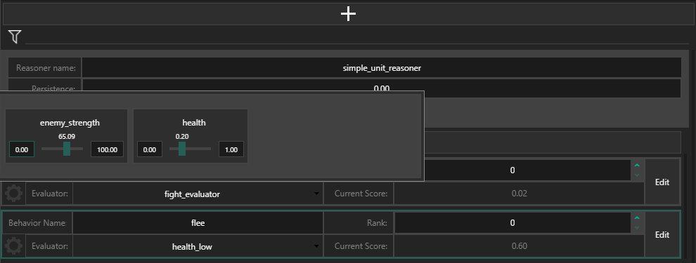
(11) Consideration value setup - after clicking on this button a popup will be displayed that allows you to set the values of considerations used by the behavior’s assigned evaluator and see how they affect the overall score.
(12) Edit button - after clicking on this button, the current column will be switched to Evaluator Designer for the currently assigned evaluator.
(13) Current score - here you can enter the behavior’s utility score, given the set consideration values. The behavior with the highest score will be highlighted.
Evaluator List
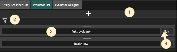
In this view, you can create and name new utility evaluators.
(1) Add button - creates a new evaluator.
(2) Filter - allows you to filter the displayed evaluators by name.
(3) Evaluator name text field - here you can enter the evaluator’s name.
(4) Edit button - after clicking on this button, the current column will be switched to Evaluator Designer for this evaluator.
Evaluator Designer
(1) Evaluator name text field - here you can enter the evaluator’s name.
(2) Evaluator dropdown - here you can select the evaluator to edit.
(3) Consideration foldout - after expanding, allows you to set the values of considerations used by the evaluator and see how they affect the evaluation flow.
(4) Evaluator Tree View - allows you to display and edit the inner structure of the evaluator, by connecting various types of nodes. These nodes come in one of four types: consideration, curve, Aggregator and evaluator reference. More about using each of those types below.
(5) AutoLayout button - automatically calculates a clean layout for the evaluator’s tree.
Step by step guide
Now that we’ve got the basics covered, it’s time to setup our utility reasoner!
Create a utility reasoner
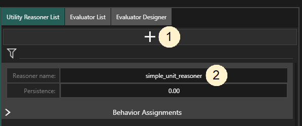
To create a new utility reasoner, switch to Utility Reasoner List view and click the Add button (1).
This will create a new reasoner with automatically generated name.
You can edit the name (2) to customize it to your game and it is a good idea to do it.
Let’s name our Reasoner simple_unit_reasoner.
Create behaviors
Let’s create some behaviors to work with. The utility reasoner will be computing utility values for these behaviors, after all.
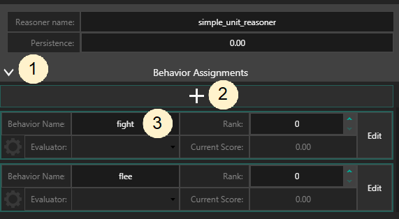
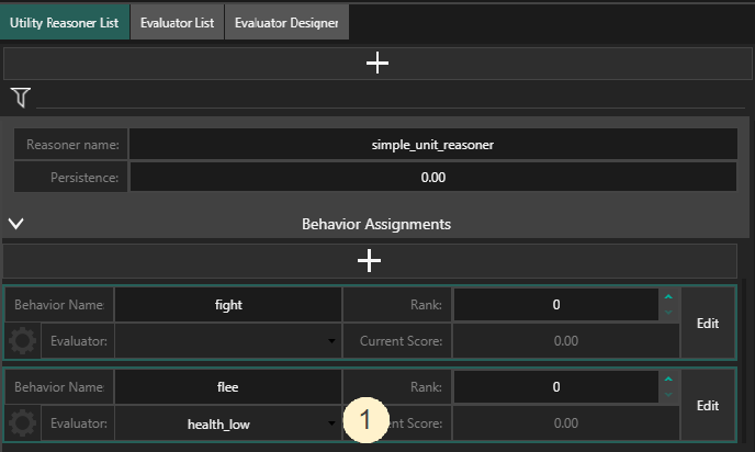
To create behaviors, expand the behavior Assignments foldout (1) and click the plus sign (2).
Click the newly created behavior’s name (3) to edit it.
If you load the configuration file in the game, the names will be matched with behavior blueprints defined in code, so make sure the strings are identical.
Let’s create two behaviors named fight and flee.
| If you opened an existing configuration file, there is a chance that there are some behaviors already defined. You will see an already populated list then. |
Create and configure evaluators
If we want our agent to behave properly, their behaviors should be evaluated based on the observed world state. For this to happen, we have to create some evaluators.
Let’s say we want our agent to flee when their health is low and fight when it isn’t, given that enemy strength is not too high.
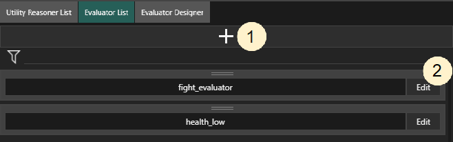
Switch back to the Evaluator List tab and click the plus sign (1) to create new evaluators.
Let’s create two evaluators named health_low and fight_evaluator.
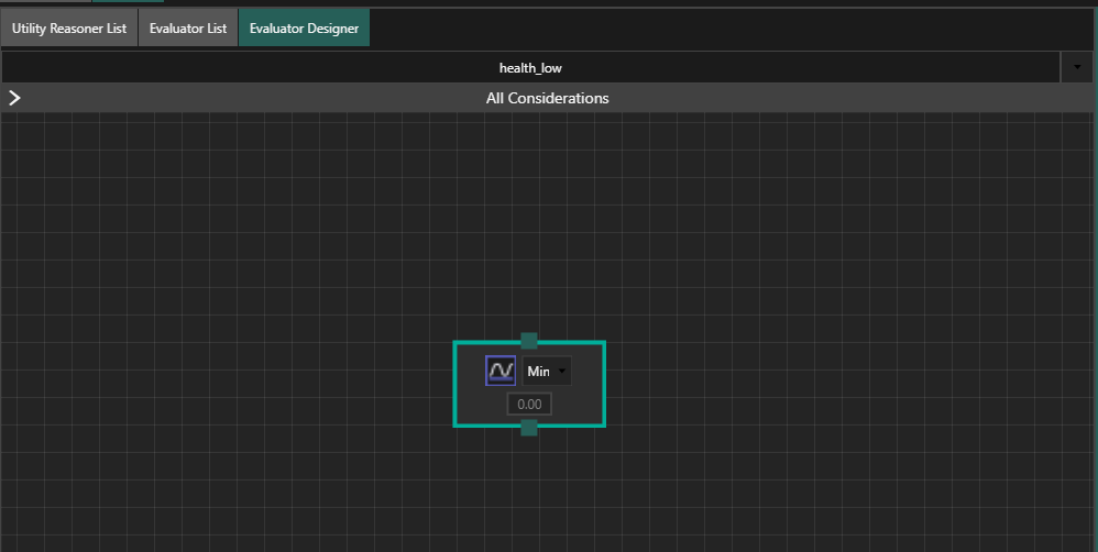
Click on the Edit button (2) on health_low evaluator to automatically switch to Evaluator Designer view.
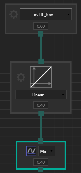
You should see a simple evaluator tree, consisting of just a single Min aggregator node.
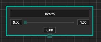
You can remove the default node as we won’t need it anymore. Right click on an empty space and select Create Node → consideration. A new node should appear. Enter 'health' in it’s text box. Let’s assume that health can range from 0 to 1. You can enter those values in the text boxes to the left and right sides of the value slider.
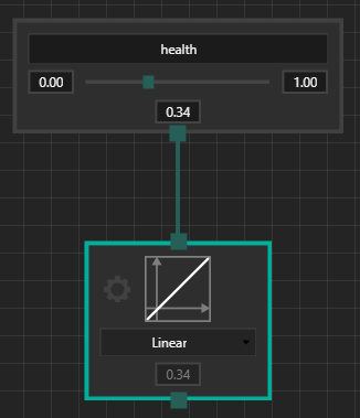
Now that we have the consideration defined, we have to tell our agent what 'low health' means. To do this, we’ll use a curve node. Right click on the empty space and select Create Node → curve. Then create a connection between the two nodes by dragging from the considerations output to the curve’s input. You should notice that after connecting the nodes, the curve node got highlighted. This means that it became the evaluator’s root node, meaning that the evaluator’s overall output value will be determined by this node. You now can try to move the consideration’s value slider to check how it gets transformed by the curve.
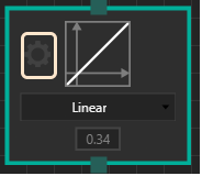
As you’ve probably noticed, the curve does nothing to the consideration’s value. It’s time to change it. Rememeber, we want to express the concept of low health with our evaluator! Click on the gear button on the curve node. A Curve Editor popup should appear. In this editor, we are can adjust the curve to our liking.
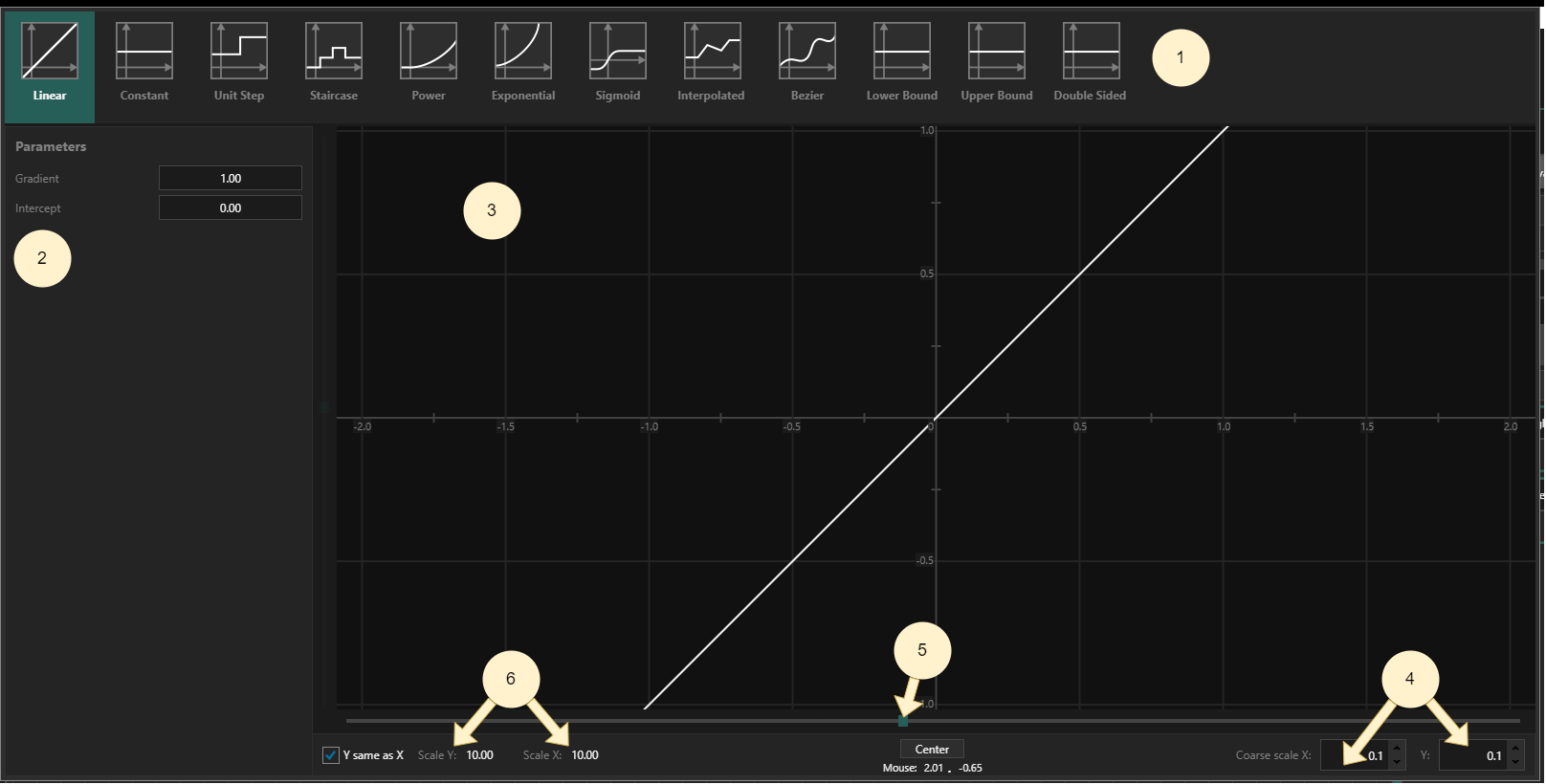
The most fun part of the whole process is to configure utility curves, so let’s get to it! But first, let’s describe the popup’s contents.
(1) Curve type selector - here you can select the base type for your curve. It’s the first thing you should do.
Currently, Grail supports the following types of curves: Linear, Constant, Unit Step, Staircase Power, Exponential, Sigmoid, Interpolated Linear, and Bezier, Lower Bound, Upper Bound, Double Sided Bound.
(2) Curve parameters - this is a context-based panel that is specific to the chosen curve’s type. You can enter its parametrization here. For example: the Step curve allows you set where the step is (Threshold parameter) and what values the curve takes before and after this step.
(3) Curve view - the curve is plotted here, so you can analyze what values it takes for a given X. Some curves, i.e. Interpolated Linear and Bezier, can be edited here by dragging control points.
(4) Scaling settings 1 - you can see the scale for the plot. This is just for viewing convenience. By default the scaling is equal in both X and Y directions. If you want to change it, uncheck the Y same as X box. This will make the scaling slider appear for Y axis too.
(5) X scaling slider - you can use this slide to scale the view along the X axis.
(6) Scaling settings 2 - you can also enter a multiplier for the scale in X and Y axes, respectively. This is just for viewing convenience. For example, if you change the scale X from 1 to 10 you will zoom out the plot 10 times.
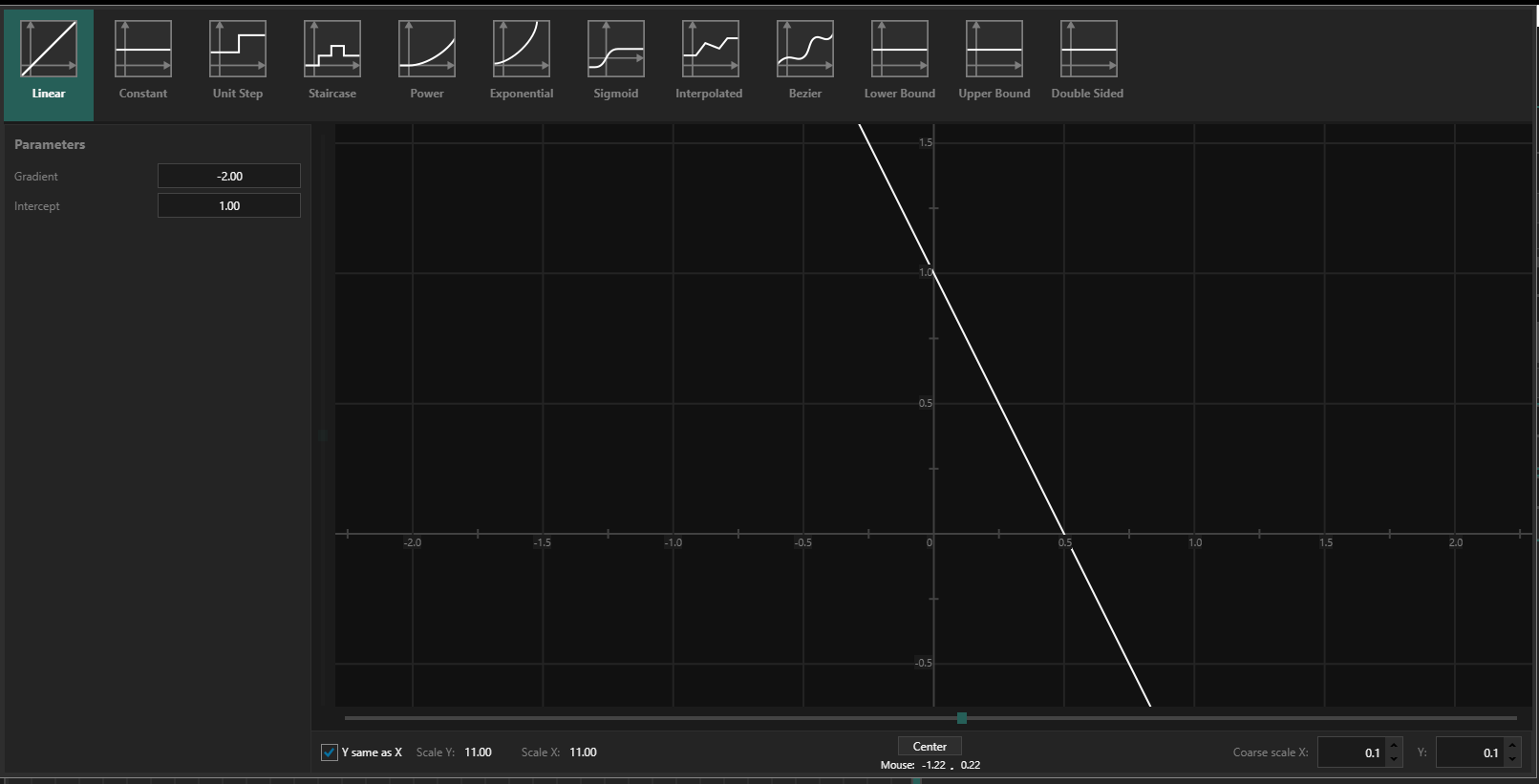
Let’s set our curve’s type to linear, it’s gradient (slope) to -2.0 and intercept (crossing with the Y axis) to 1.0.
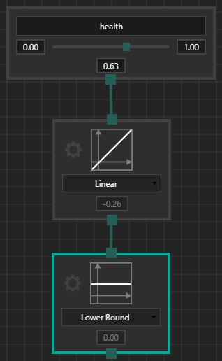
We’re almost done here, but we don’t want our output value to go below zero, as it can make things confusing. Let’s add an additional Lower Bound node and connect the first curve to its input.
To add the curve, simply create a new curve node and select the desired type (Lower Bound) from the dropdown. Make sure that it’s Min Value parameter is set to 0.0.
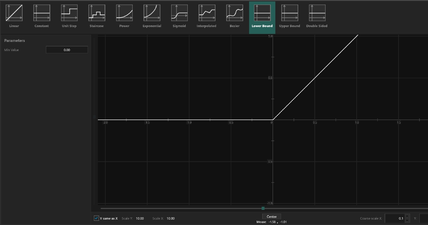
Now, while moving the consideration node’s value slider, you can see that evaluations are high for low health values and low for higher ones.
Now let’s go to Utility Reasoner List view and assign the newly created evaluator to flee behavior by selecting it from the dropdown (1).
An alternative way to do this is to open Evaluator List in one column, Utility Reasoner List in the other and drag evaluators from the list on behavior entries.
Now let’s proceed to defining the evaluator for fight behavior.
We decided that our agent should select this behavior when their health is not low and enemy strength is not too high.
But wait, does it mean that we have to go through all the pains of expressing the concept of 'low health' all over again?
Fortunately no, as you’ll see in a short while.
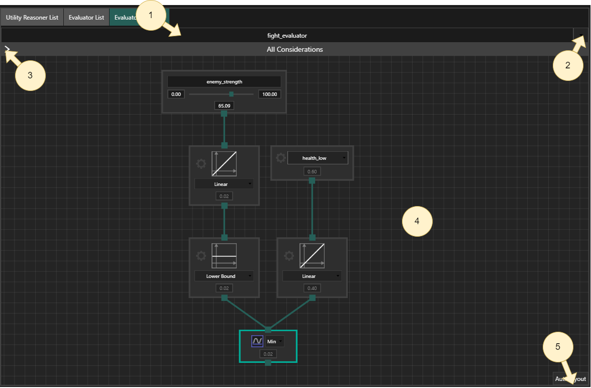
Switch to Evaluator Designer and select fight_evaluator from the dropdown.
Just like before, you should see a single default node already added.
This time, we’ll leave it in place.
If we want to reuse the already defined concept of low health, we can resort to another node type - evaluator reference.
This type of nodes allow us to reuse whole evaluator trees as would-be considerations.
Now add a evaluator reference node by right clicking on empty space and selecting Create Node → evaluator reference.
Then, you can select health_low evaluator from its dropdown.
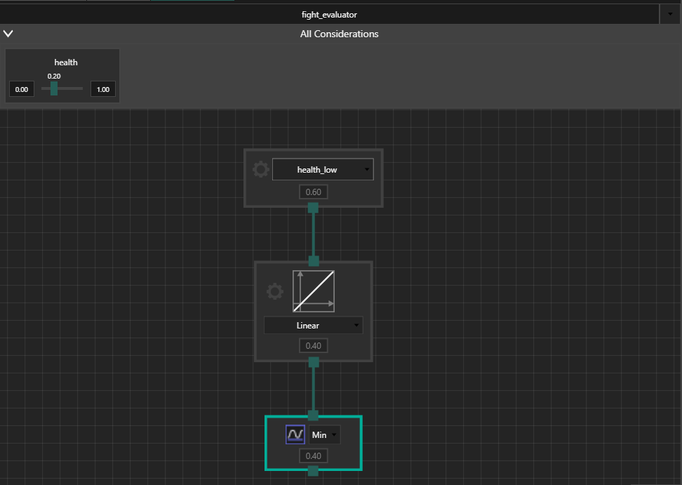
Before we connect the node to the output aggregator, we want to express a negation (health NOT low).
To do this, simply add a Linear curve with with gradient set to -1.0 and intercept set to 1.0.
This way, we’ll get low evaluations when health_low returns high value and vice versa.
Although you can’t directly see the considerations used by referenced evaluators, you can still manipulate their values to debug your configuration.
Simply expand the All considerations foldout and give it a try.
Now it’s time for the second condition (enemy strength not too high) to be expressed.
You already know all the basics, so you should be able to do this on your own.
Create an enemy_strength consideration, set its min and max values to (these are example values) 0 and 100 respectively, create a Linear curve with gradient set to -0.015 and intercept set to 1.0 and a Lower Bound curve, connected as follows:
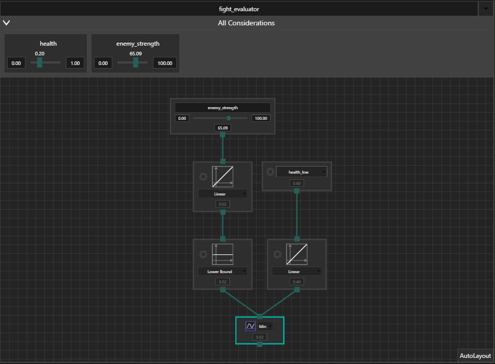
As you can see, the enemy_strength consideration also appeared on the All considerations preview list.
Test the system
Now we can assign the new evaluator to fight behavior just like we did with flee and test if the system is operating properly.
-
consideration sliders- after clicking on the cogwheel button on a behavior panel, all considerations used by the behavior’s evaluator will be shown. You can change the values of considerations just like we did when designing evaluators. This way, you can emulate the game state in a simplified fashion and observe which behavior gets selected. You can test whether the system meets your expectations.
Testing utility System is a process similar to debugging. Here is the manual page for utility Debugger.
Utility reasoner assignment
This topic is covered in tutorial: Entity Creation Tools.
You can drag the reasoner onto an entity in the Entity Editor tab.
Using the configuration in your game
In order to use the system created in this editor, save it to the configuration file and load it in your game. Please go through the following tutorial: Configuration Loading.